
An unsafe restart occurs when energy, motion, material flow, or an automated sequence returns before the machine and surrounding area have been verified as ready. The immediate trigger may look simple: a guard is closed, a reset button is pressed, or a controller receives a start command. The underlying failure is usually a broken connection between several safeguards that were treated as separate tasks. Industrial equipment safety integrations prevent this gap by requiring physical conditions, isolation status, control logic, and restart authorization to agree before hazardous motion is permitted.
A restart command should never be interpreted as proof that a machine is safe to run. It is only a request. A well-integrated system evaluates whether protective devices are restored, energy isolation has been formally released, stored energy is controlled, the hazardous zone is clear, and the process is in a valid state. Where any one condition is uncertain, the command must remain blocked or lead only to a controlled recovery state rather than normal production.
Restart safety depends on the state transition, not the stop command
Many machines can stop safely yet still restart unsafely. A conveyor may stop because an emergency-stop circuit opened, but its elevated carriage can remain held by pneumatic pressure. A printing press may halt after a guard door opens, while web tension, heated rollers, and automatic splice logic remain active conditions that require separate verification. On a packaging line, a photoelectric sensor may confirm that a gate is closed without confirming that a technician has left the guarded area.
For this reason, the safety function must distinguish among stopping, isolating, resetting, and restarting. These states have different purposes:
- A protective stop removes or prevents hazardous motion in response to a safeguard or emergency action.
- Energy isolation supports maintenance by disconnecting or controlling electrical, pneumatic, hydraulic, thermal, gravitational, and other energy sources.
- A reset acknowledges that a safety device has returned to its expected condition; it must not by itself cause motion.
- A restart is a deliberate production command accepted only after the logic has established a safe and valid machine state.
Combining these states into one pushbutton sequence is a common source of unsafe restart events. If resetting a guard interlock also restores an automatic cycle, a person may be exposed before recognizing that the cycle is armed. A reset should clear a fault only after the cause has been addressed. A separate start action, located so that the hazardous area can be observed where required, creates an intentional break between recovery and movement.
Interlocks must verify the protection function they are meant to support
Guard interlocks are often misunderstood as simple door switches. Their real value comes from the safety function around them. A hinge-mounted guard that has shifted over time may still actuate an ordinary switch while leaving an opening large enough for access. A coded, non-contact interlock may resist simple defeat, yet it cannot establish safety if the guard panel is cracked, its latch does not hold, or a second access route remains open.
The choice of interlock must match the guard construction and the hazard behavior. Guards surrounding high-inertia equipment need a means to prevent opening until rotation reaches a safe condition. This may require guard locking linked to a monitored stopping function. Conversely, applying locking hardware to a low-risk access cover without considering emergency escape or loss-of-power behavior can create a different hazard. The release method, escape provision, and fault response need to be assessed alongside the stopping time.
Signal interpretation also matters. A closed contact does not always mean a closed guard, and a closed guard does not always mean no access. The logic should use monitored safety inputs designed to reveal conditions such as wire breaks, shorts, invalid actuator alignment, or discrepancies between channels. Diagnostic messages should identify the actual source of the inhibit: guard open, lock not engaged, speed not at zero, reset pending, or a process permissive unavailable. A generic “machine fault” message invites hurried bypassing because it conceals the condition that must be corrected.
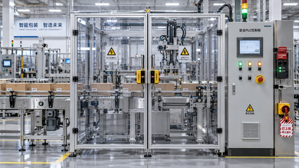
Safety PLC logic creates a controlled restart envelope
A safety PLC or safety relay does not make an installation safe merely because it is present. Its value lies in executing defined safety functions and preventing ordinary control logic from overriding them. The safety controller receives monitored inputs from emergency-stop devices, guard interlocks, light curtains, enabling devices, speed sensors, pressure switches, and other relevant devices. It then permits or removes energy through safety-rated outputs, contactors, valve arrangements, drives, or safe torque off functions.
The central design question is: what conditions must be true before each type of restart? The answer changes across equipment modes. A full automatic restart after a production pause may require all perimeter guards closed, no active protective-device demand, a valid material path, drive feedback, and a deliberate start command. A maintenance or setup mode may allow limited motion at reduced speed through a hold-to-run enabling device, with automatic sequencing disabled. Treating every restart as equivalent either makes the system unnecessarily difficult to use or leaves hazardous modes insufficiently controlled.
Mode selection deserves close attention because many unsafe events occur during adjustment rather than normal output. A selector mounted inside an enclosure, a software mode protected only by a common password, or a mode change that leaves previous automatic commands queued can defeat the intended separation. Mode changes should be clearly indicated, controlled through the safety architecture where appropriate, and designed so that a transition back to automatic mode requires a fresh start request. A command retained in a standard PLC memory register should not wake a machine after guards are restored.
Feedback monitoring closes another important gap. If a safety output requests a motor contactor to open but welded contacts leave power available, the controller needs feedback indicating that the intended de-energized state was not achieved. The same principle applies to dual valves controlling pneumatic motion and to brake-monitoring arrangements on vertical or high-inertia axes. Without feedback, the system can display a stopped condition while the machine retains the ability to move.
Lockout/tagout and automation must exchange an unambiguous status
Lockout/tagout is an energy-control procedure, while machine safety controls manage operational hazards. They overlap during maintenance, but one should not be treated as a substitute for the other. A safety-rated stop does not necessarily isolate electrical supply, bleed pneumatic pressure, block gravity, or restrain a suspended load. Equally, an isolation device being restored does not establish that guards, tools, and process conditions are ready for automatic operation.
An integrated restart arrangement makes the handoff visible. During maintenance, lockout points and stored-energy controls establish the equipment’s isolated condition. Before normal control can be restored, the release process must include inspection of the affected area, removal of tools and temporary restraints when applicable, replacement of guards, and confirmation that all assigned locks have been removed under the site procedure. The automation system should then remain in a restart-inhibited state until an intentional reset and start sequence occurs.
Digital status signals can support this handoff, but they should be used carefully. An auxiliary contact on a disconnect can report switch position; it cannot prove that an individual lock has been removed correctly, that a hydraulic accumulator is depressurized, or that a blocked ram has been mechanically secured. A maintenance permit system can record task completion; it cannot independently verify that a trapped person is not inside a machine. Electronic information is valuable when it reflects a real, validated condition rather than becoming a substitute for physical verification.
Process state verification prevents the wrong kind of restart
Even after personnel protection conditions are satisfied, an immediate return to normal speed may damage equipment or create an unstable process. Safety integration should therefore coordinate with machine-state verification without allowing ordinary process controls to dilute protective functions. The distinction is important: a process permissive may prevent scrap or equipment damage, whereas a safety interlock prevents exposure to harm. Both may block restart, but they require different design assumptions and different validation.
Consider a paper converting line after a web break. Guards may be closed and the emergency stop reset, yet adhesive, paper stock, cutting blades, and driven rolls may not be in a state suitable for automatic restart. The sequence may need a slow, supervised threading movement before full production is permitted. On a textile machine, yarn entanglement or a removed cleaning tool may require a setup mode rather than an automatic start. In a thermal packaging process, a cooling interval or temperature condition may be needed before material can be moved safely through sealing components.
These examples show why a single green “ready” indicator is often too broad. Clear status differentiation reduces incorrect recovery actions. Useful distinctions include safety condition restored, energy isolation active, manual mode selected, automatic mode available, process not ready, and start request accepted. The display should not imply that a machine is safe to enter merely because production is unavailable; a faulted drive, a suspended load, or residual pressure may still present a hazard.
Validation must test realistic faults and abnormal recovery paths
Testing only the intended sequence provides limited confidence. Restart protection needs to be challenged with conditions that occur during installation, cleaning, repair, and production disturbances. This includes opening a guard during motion, restoring a guard before the machine has stopped, loss and return of supply power, a failed sensor channel, an interrupted reset, a drive fault, and an attempt to restart from a remote control station while access is possible.
Validation should follow the actual installed configuration, including cable routing, actuator alignment, valve plumbing, drive settings, and access geometry. A sound control drawing cannot compensate for an interlock mounted where vibration causes intermittent alignment, a safety relay wired through an unmonitored bypass, or a pneumatic valve installed with ports reversed. Changes to guards, tooling, control software, motor drives, operating modes, or line layout should trigger a review of the restart function because a small modification can change stopping behavior or create a new access point.
Bypass control is part of the safety design
Temporary bypasses are sometimes necessary for diagnosis, setup, or controlled maintenance, but an undocumented bypass converts a designed safeguard into an assumption. The system should make bypass status conspicuous, restrict it to a defined mode or authorization process, limit the permitted motion, and prevent a silent return to automatic operation. A bypass that survives a power cycle, shift change, or controller restart is particularly difficult to manage because the machine may appear normal while a protective layer is absent.
Repeated bypass requests often reveal a design issue rather than a discipline issue. Nuisance trips can arise from misaligned guards, contaminated light-curtain optics, inadequate cable protection, unstable material presentation, or process steps that require access more frequently than the original layout allowed. Recording the specific safety function involved and the operating condition at the time of demand helps separate a genuine safety-device fault from a production process problem.
Reliable restart prevention is built from verified physical protection, monitored control logic, disciplined energy isolation, and a restart sequence that demands deliberate human action. When those elements share a coherent state model, a machine does not move merely because a fault disappeared or power returned. It moves only after the conditions that made access hazardous have been demonstrably resolved.
Related News
- Commercial Insights on Global Emerging Markets in PrintMay 14, 2026Global emerging markets insights for print businesses: discover high-potential segments, entry strategies, and risk signals to improve timing, reduce uncertainty, and win faster in growth markets.
- Greening Manufacturing: Which Projects Pay Back Faster?May 14, 2026Greening manufacturing projects that pay back fastest often cut energy, waste, and downtime in 6–24 months. See which upgrades finance teams should approve first.
- Choosing food safety compliance training programs for audit readinessOct 20, 2026Compare food safety compliance training programs for audit readiness. Learn how to verify practical skills, assess providers, and secure traceable records before you invest.
- How to select industrial components for heavy-duty shock loadsOct 18, 2026Select industrial components for heavy duty use with confidence. Learn how to assess shock loads, compare ratings, and verify assemblies to reduce damage and costly downtime.